Microtron Design History, Part 1: Voigt Vision
Look, I’m just a guy who is trying to sell you bespoke electronics, which is, you know, a bit of a tricky proposition. One thing I’m going to do to build up your trust and excitement in the Microtron is walk you through the evolution of the Microtron, talk about how it works, show you some pictures of the guts and the improvements over time. We’ll start at the beginning with the original concepts and prototypes, and work our way forwards to today with the finished product. Part 1 will cover the beginnings and prototypes, and part 2 will be an in-depth look at the Microtron that’s on sale now. Let’s get started!
The First Microtron, aka Voigt Vision
Some friends of mine had made “Bat Signals” for their office, which were made of LED panels and a rotating beacon light that could be used to broadcast messages to all the employees. Important messages like “hey we’re all having a beer now". Seeing this gave me the idea to try to replicate Fenway Park’s famous manual scoreboard out of LED panels. The original Microtron was called “Voigt Vision”, because, like they say, always be self-promoting.
The “VV1” for the model is “Voigt Vision 1”. Voigt Vision 2 is just The Microtron.
There are a few components you need in order to be able to serve up scores:
A data source, e.g. somewhere you can get close to real-time scores and stats
Some form of computer that can access the internet/data source, and also output a signal that the LED panels can use
LED Panels. These panels use a HUB-75 connector (which is a 16 pin ribbon cable connection), not HDMI or anything like that
A power supply to power the LED panels and the computer
Something that holds them all together
The Data
There are a number of sports APIs out there (for non-computer programmers, an API is basically a service on the internet where a computer can make a request for data, and get that data back… for computer folks, sorry for that not-exactly-precise definition). MLB has one that’s undocumented (meaning that there’s no guide that tells you how to request the data, or what that data will look like) but pretty straightforward to figure out with some guesswork, so that’s what I used for Voigt Vision. You can see what that data feed looks like here.
The Computer
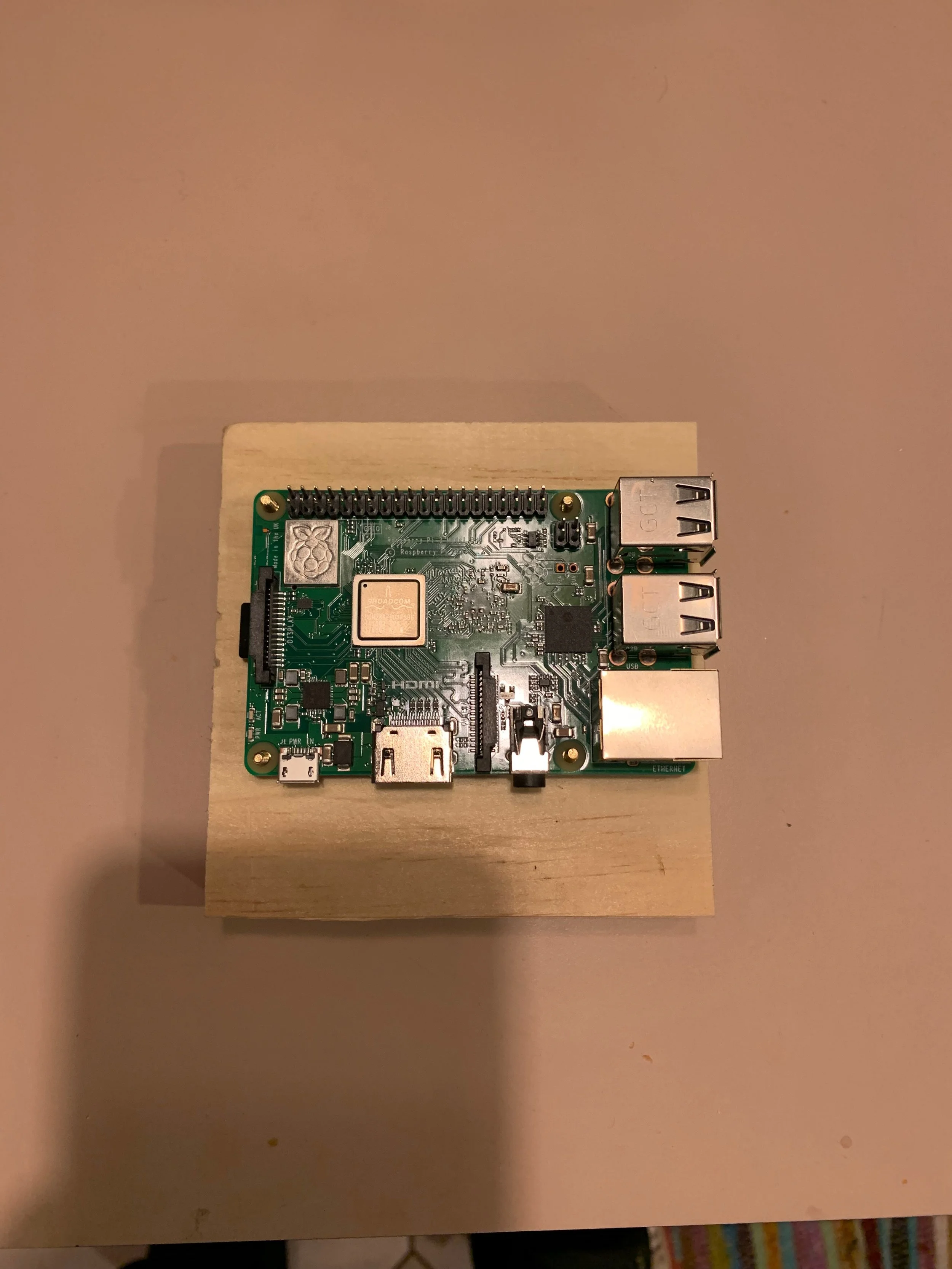
Obviously, I didn’t want to put a full windows PC in a scoreboard box, but luckily, there are a ton of great small, cheap, full-featured computers out there. The folks who made the Bat Signals used a Raspberry Pi, so that’s what I went with. A Raspberry Pi is an inexpensive computer board (around $40) built around a cell phone processor. It doesn’t have a ton of computing power, but it has more than enough. Crucially, they’re easy to hook up to all sorts of peripherals. They have USB ports, but they also have GPIO pins (GPIO = General Purpose Input/Output), which you can hook up to pretty much anything via a “hat”, or secondary circuit board that sits on top of the Raspberry Pi. Adafruit makes a hat for driving the LED panels that has the correct connector to plug directly into the panels, so the Pi + LED Matrix hat took care of the computer.
The LED Panels
There are tons of LED panels in common form factors out there (e.g. they’re all the exact same dimensions and take the same power/signal cables), all made by a bunch of different companies in China (none of these companies are household names). All the ones you buy, even through Adafruit, are essentially going to be random panels from China (the Adafruit ones just have a bit of branding on them, and some extra price markup). There are subtle differences in the onboard circuitry, so it’s a bit of a crapshoot to make sure you’re getting good panels that will work with the existing panel driving software out there. So, you basically take a shot on some well reviewed panels from AliExpress, and hope for the best.
The first set of panels I played around with were 32x16 pixel panels, and those were simply too low res to do anything with. I tried a few scoreboard type things, but you just can’t fit enough information on those, even when I used 4. They’d be great for something like a display that scrolled a simple message across it, but for anything with actual graphics, they just don’t offer enough complexity to be useful. I eventually settled on the 64x32 panels, which, although still constraining, do allow you to fit a reasonable amount of stuff. From the outset, I wanted to have 4 panels, as that size just felt right to me.
Below, you can see the original 32x16 panels, then some early attempts at layouts, as well as one of the first boxes I built for it. The actual layout for baseball is pretty close to this!


The Power Supply
Raspberry Pis are easy to power: hook them up to USB, and they’re pretty much good to go. LED panels, on the other hand, are not. They require some decent amounts of power, and they have wires terminated with spade lugs that you can’t just plug into a USB jack. Luckily, both the Pi and the LED panels require 5 volts, so you can hook them up to the same power supply, provided that that power supply has enough juice. Of course, most don’t. The standard “wall wart” power supply usually only puts out only 2-3 amps, max, and the panels need more that per panel. The exact amount they need is tricky, because it’s directly related to what they’re showing. If they showed bright white on every pixel, that would require the maximum amount of power, but on average, they don’t need that much. Their rated max power is 5A, so I was looking at a minimum 20A supply for the panels, plus a bit more for the Pi. When building Voigt Vision, I wanted to make sure that I wouldn’t overload a power supply at any time, so I went big.
The beefiest power supplies are pretty industrial looking, designed to be mounted inside somewhere. I found this 5V 30A one, and ran with it. The plan was to mount it inside the box, and run 120V AC wall current into the box. I’m not sure why I didn’t look at the beefier external laptop style supplies at the time, but I’m guessing it’s because I wanted close to 30 amps, and no one’s getting that from a laptop brick. The fact that I was running wall voltage into the box is by far the biggest negative of this design. While it’s not de facto a fire hazard, it wasn’t NOT a fire hazard. You can see the power supply in the first image in the set above, just chilling on my desk.
The Box
I wanted to make a box with mitered corners, however, there are a few problems with miter joints. The biggest one is that they are hard to make precisely and glue up well. It’s certainly doable, but the Voigt Vision box is a far cry from being precise. The panels have a lot of wiggle room and gaps around the edges (as you can see in the images below).
The other issue I had was how to mount the panels in the box. They came with little magnetic feet that could hold them on a piece of metal, so what I did was install two metal rails that the panels could stick to (this was actually the 2nd try, the first try had me embedding magnets into wood directly). For mounting the Pi, I glued some brass standoffs into the wood, and then attached the Pi to those. There’s a lot of wood in the original box glued up in complicated ways, it had mains voltage running into it, and there was no back. There was functionally no way I could have ever produced that box at any degree of scale, nor felt comfortable selling it.
Below, you can see some of the original boxes, including the glued in magnets, the Pi mounting system, and the problems I had making a mitered box that was even close to being the right size:


The Voigt Vision
Once I had everything together, it was a matter of writing some software that could download some data and draw the scoreboard. While it seems fairly straightforward in theory, in practice, as any good software engineer will attest, things are always more complicated than they first appear. I won’t go into all of the particular challenges here (and truthfully, I forget some of them, as I built this box almost 4 years ago at this point), but the biggest hurdle to turning Voigt Vision into a sellable product was that the Pi is actually a full computer. This means it needs time to boot up, you can’t shut it off randomly, and since it was doing all the layout work of the scoreboard itself, if you ever wanted to change what people’s scoreboards would update, you’d need to remotely install new software on the Pi (or have the user manually upgrade).
The Problems
To recap, there were some pretty big problems with the original Voigt Vision:
It ran mains AC power into a wooden box, which is not NOT a fire hazard
The box itself was hard to build, complicated, and not particularly tight with tolerances
The user experience of having a full computer in the box wasn’t good
Updating the software was going to be a huge pain
So, taken together, the original Voigt Vision wasn’t really sellable. I wouldn’t even want to give them out as gifts, they were just too limited. BUT! And this is an important but! It worked! It looked super cool, it would show scores, it got rave reviews from everyone who saw it. Still, with the outstanding issues, I wound up setting it aside for a while. In the meantime, I got a proper garage workshop set up, started building all sorts of things out of wood, and wound up neglecting the poor Voigt Vision. Then this year, on opening day, I hauled it out of the closet, plugged it in, turned it on, got it up and running, and remembered that it was, in fact, pretty freaking sweet. I just had to figure out how to make it, you know, good. Spoiler alert: I didn’t just make it good, I made it great. Stay Tuned!

The original Voigt Vision 1 on opening day, 2022. Good enough to inspire me to make it great!